title Image for Rehab Engineer main page
RTS Information (password required)
Link to my list of bookmarks
Link to Section 508 Information
Link to Case Study Index
Link to my Resume
Link to my design projects
Link to Technology Watch for this month
Link to upper body ergonomics pages
link to page on making web sites accessible
Augmentative Communication Information Site
Job opportunities in the field of assistive technology
e-mail me
Leonardo DaVinci's Vitruvian drawing
This information is provided "as is" without warranty or any kind, either expressed or implied, including, but not limited to, the implied warranties of merchantability, fitness for a particular purpose, or non-infringement. In no event shall RehabEngineer.Homestead.com or Michael Papp be liable for any direct, indirect, incidental, punitive, or consequential damages of any kind whatsoever with respect to the service, the materials and the products referenced in these documents. This applies to all pages on this web site.

PicoSearch Help
Site Map
Link to RehabEngineer
Job Accomodation Network
Access Board
Technical Assistance Projects
This page was last updated on: 23 October, 2012
Auditory Environmental Control Unit
Design problem:
A patient has need of an ECU that automatically scans five selections when activated by a sound.  During the scan it is to provide some type of audio output that informs the patient what selection is available.

The Solution:
This is the second interation of the circuit design. This package is designed to fit into a surge protector type enclosure, with a separate microphone that is plugged in and places away from the surge protector so there is no feedback.  Changed aspects of this design are flip-flop latches for the relays, an additional line driver between the decade counter and the AND gates and relays it needed to drive, and a new voice switch. These improvements were made because we wanted to latch the relays open or closed after a control signal was sent. The line driver was added because the output of the decade counter was not enough to drive both the relays for the changing tones and the and gates to signal the actuation of one of the output relays. The new voice switch was added because the old design was not working, and this design was easier to implement. All these changes made the circuit work a lot better. The only problem with this current design is sometimes there is some sort of feedback into the voice switch that will not allow it to shut off. One further improvement that may be made is to automatically turn off the mono-stable timer after the decade counter switches off the last audio signal, instead of having the decade counter time out like it currently does.
ABLEDATA
Computer Access
Rehabilitation Engineering Research Centers (RERC)
Design Projects | Ergonomics | Section 508 | Case Studies | Qualifications | RTS Info
Tech Watch | Links | Accessible Web Design
Augmentative Communication | Augmentative Communication Computer Hardware | Contact
The 5 count timer runs until the monostable timer times out. It is set to time out after the last tone has finished, but before the first tone starts again.
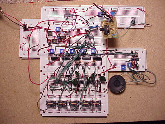
How it works:
A separate microphone is plugged into the device.  The microphone can be position in an appropriate location to detect sound.  The microphone feeds sound into an voice activated switch (VOX) (see figure 3). This switch reponds to frequencies in the human voice range or hand claps. When a sound is passed, a mono-stable timer enables a 5 counter circuit to start scanning selections for a predetermined time (a pot adjusts the length of time). The output signal of the 5 counter goes to a line driver. From the line driver output drives a relay which activates an audio circuit built with a 556 timer, and one input of an AND gate.  The relay adds different resistances into the circuit, modulating the frequency of the tone produces.  When the tone corresponding to the desired selection is made, the user makes another noise in the appropriate frequency range for the VOX. The signal is passed to the other input of the AND gate. When both inputs are high, the AND gate sends a signal to a J-K flip-flop latch that turns a relay on or off. The relay switches AC current, and any device hooked up to the relays output is activated or deactivated.
Image of Audio Scanner circuit on bread board